Multimedia Quality Tools Training & Toolkit on your PC or Intranet

A Fresh Look at Flow Charting.
Introduction
Flow charting is one of the oldest quality improvement tools. As a means of documenting work practices it has been around for centuries, perhaps beginning with the scratchings of Neanderthals on the roofs of caves, documenting hunting methodologies. What have we learned and where is flow charting heading?
Definition
Firstly, a flow chart is a means of conveying information about a process. The Shorter Oxford defines it as "a diagram showing the movement or action of persons or things in any complex system".
Many quality professionals are unaware of the ISO quality standard that describes flow charts, ISO9004.4. Section A.6.2 describes a flow chart as "a pictorial representation of the steps in a process, useful for investigating opportunities for improvement by gaining a detailed understanding of how the process actually works...Flow charts are constructed with easily recognised symbols."
Computer Based Flow Charting
In attempting to improve the "pictorial representation", most professionals have moved to computer systems to create flow charts. The computer enables each symbol to be neatly aligned and connecting lines drawn clearly and simply. Most systems provide some means of creating connecting lines automatically. However, in using computer based flow charts, there may often be more negatives than benefits, as will be seen.
The flow chart is a means of communicating information. It must be able to communicate the steps in a process clearly and unambiguously. It must be possible for any team in an organization to examine a flow chart created elsewhere and immediately understand it. This is the reason ISO9004.4 states "easily recognised symbols".
Too Many Symbols!
Unfortunately, vendors of most computer products face other pressures. To be successful, they feel they must gain the highest ratings in magazine product reviews. They must have the maximum number of boxes in product comparison check lists filled in. To rank highest, a product must have the maximum number of features and attributes. The first most obvious result is the huge symbol libraries containing thousands of symbols of the most common flowcharters. To make matters even worse, most of these products also allow customised symbols to be created.
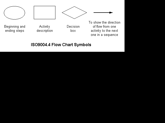
Compare the symbol libraries of the most common computer based flow charting products with ISO9004.4. The standard shows just four (4) symbols: start/end; activity; decision and flow line. See fig 1. With these symbols, any simple process can be represented unambiguously. This is in marked contrast to the majority of computer products. Thousands of symbols create thousand of opportunities for misunderstandings.

The greatest defect of all is those flow charter's ability to allow users to invent and create new symbols. Inventing symbols absolutely guarantees misunderstanding by other people.
ISO9004.4 has other benefits. People have short term memories of seven plus or minus two "things". For example, if I asked you to recall the names of your high school classmates, you would get to around seven, then slow down dramatically as you searched your long term memory. The same situation applies to flow charts. Any more than 7 minus 2 = 5, symbols and you can guarantee that there will be some people in your organisation who will begin to have difficulty remembering some of the symbols you have used. Any more than 7 plus 2 = 9 symbols and you can guarantee than almost everyone will have difficulty understanding your flowchart. The standard has a symbol set that ensures instant recognition by everyone.
Sub-Processes
The flow chart shown in ISO9004.4 is a fairly simple one. Most organisations have a need to document very complex processes. If a single flow chart for an entire organisation were to be drawn, its size would make it totally unmanageable, even for small companies. The best approach in simplifying the flow chart is to create a layered diagram that matches the way organisations are layered. In other words, the use of subprocesses is required. This allows a flow chart to be built with a top senior management layer, with each step containing complete flow charts for the next, sub - senior management layer. Steps within this layer would contain further sub-flow charts and so on. This enables process to be viewed and analysed at the level appropriate to the particular team or person. It avoids having to be concerned about either the details of a step or the macro view, when analysing a process.
Unfortunately ISO9004.4 does not provide a symbol for subprocesses. This is the only additional symbol required to fully describe any process, simple or complex, taking the symbol total to 5. Whilst the standard does not provide a symbol, it is suggested that a symbol similar to a task be used. A symbol for a task with a task behind it is a possible choice.
Flow Chart Validity Checking
The flow chart is a pictorial representation of a process. It should also make sense! Unfortunately, the power of the computer gives too much flexibility in many instances. Most computer systems allow almost anything to be drawn anywhere, connected to anything (A test: Try drawing a task with 5 lines connected to a smiley face using your favourite flow charter!) This is fine perhaps when illustrating a concept but not when documenting a process.
The rules of flow charting are fairly simple. Four examples:
- Any task has a task/subtask/decision/start/end before it and a task/subtask/decision/start/end after it.
- There is one start and it has a single outlet leg.
- Flow charts cannot have endless loops.
- A flow chart should not contain an unconnected "tag" or leg to or from a shape.
The "rules" are the natural rules of doing things, for example, one step always follows another. These rules should be built into the computer. The computer rules engine should ensure that the flow chart is logically correct. It should prevent or advise users when carrying out "illegal" operations. Unfortunately there is only a single flow charting product available today that does this.
The benefits are tremendous. A rules engine guarantees that every flow chart created in an organisation is not only correct but created in a consistent manner. Consistency and accuracy is what quality ISO standards are all about!
Process Improvement
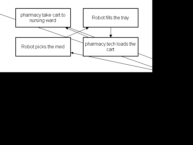
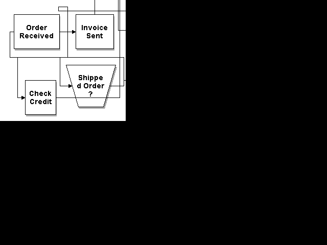
The reason for creating a flow chart is hopefully not just to document a process, but to improve it. This might involve moving steps, deleting steps or adding new steps. Surprisingly here too, many flow charters fall down. Whilst the initial flow chart looks fine, the modified one can look a mess with lines drawn through shapes or with lines looping wherever. Examples from 2 common flowcharters are shown in figs 2a and 2b. Both are almost unreadable. The flowchart in fig 2b is worst and contains overlapping lines between different pairs of shapes; a line loop; a line through text; and broken text on a non-standard shape!


The reason for the errors in the flow charting packages described above is simple. To create a "neat" flow chart with shortest length lines requires sophisticated line routing software, similar to that used in printed circuit board design. Most flow charting packages do not provide this.
ISO9004.4 section A.6.3.2 also states that the flowchart should be dated. The reasons should be fairly obvious. Dated records allow fool proof comparisons of the process situation before and after improvements. Whilst computer files may be dated or files may have attached summary information, the date should be printed with the flowchart. Many flowcharting packages forget this simple action.
Documenting Processes
The flow charter is a means of graphically describing the steps in a process. In addition to a description, there is commonly an array of other information associated with each step. For example, it may be useful to store the number of defects associated with each step, a safety rating, test equipment used, the person or people responsible for the step and so on.
The flow chart may act as a repository for associated information but it may also be useful to be able to produce a report in Word processor form, on any of the stored data. For example, an MS Word document may be produced to form part of an ISO9000 manual, or a defect rate report may be produced.
Computer based flow charters are beginning to emerge that address these needs however a majority of companies use the more popular flow charters with "cobbled" solutions using a variety of products trussed together with home grown software.
Automatic Documentation Generation
A process manual that is written by hand is often out of date the day after it is created. As soon as a change is made to the manual corresponding to a process change, the only way to absolutely ensure the accuracy of the document is to re-check the whole document. Unless the whole document is rechecked, it is impossible to ensure that an incorrect cross reference exists to the place where the change was made.
Automatic validity checking of the flowcharter coupled with automatic documentation generation prevents this problem. It ensures that printed documentation is always accurate and consistent. Automatic validity checking ensures there are no "black holes", that is, references to non existent paragraphs.
Intranets
As well as generating paper documentation, generating Intranet documents has even greater benefits. It is most time consuming to track a path through a paper based procedure or even such a document on a word processor. When the document is generated in Intranet, HTML (Hypertext Markup Language) format, click on a "Go To" immediately takes the reader to the next step in the process. All associated details of the step, such as defect rate, process owner, may be displayed. Clicking on the next "Go To" leads the reader on, whether it be to another step in the same process, or a completely different document. Backtracking the path is also a breeze, by clicking on the "Back" button shown in fig3.
Fig 3 shows an example of a simple Intranet based flowchart, viewed using the Netscape Intranet browser. Note that "If 'Yes' go to step: 6" appears in a different color, indicating that the user has clicked on this path recently. Clicking on "Subprocess title: Choose tea" immediately opens the related flowchart. This is far quicker than searching for paper based documents or even accessing cross-referenced file names with a word processor.
Several computer based flow charters are now claiming Intranet output.
Time and Cost Calculation
In addition to representing what a process does, a number of specialised flow charters are available that can represent how it does it. In other words, they can model process flows. This has the potential to be of great benefit in cost-of-quality analyses. It allows the cost of quality improvements to be analysed directly. Unfortunately most such products are very complex and quite costly. Some products in this category are extremely complex. For example, some allow complex distribution functions for times or costs for each step in a process. The cost and time required to obtain the data necessary to characterise such functions could only be justified with very major and expensive process changes. Most are less well suited to the typical quality improvement teams.
Improvement teams will benefit most by a product that allows a simple entry of the estimated time or cost for a process; calculates the overall time and cost; then ripples those cost through subprocesses.
The Ideal - Ease of Use
The ideal flow charter for process improvement teams should incorporate most of the features described above but still be easy to use. By far the greatest complain we have heard from clients is the difficulty that most teams have in using computer based flow charting. It should be possible for even unskilled team members to re-arrange a few tasks without having to worry about line drawing problems such as shown in figs 2a and 2b. Most vendors have tried to squeeze in too many irrelevant features. For example, is it really necessary for a user to be able to select solid vs hollow arrow heads, or should users simply follow the standard? Such features add unnecessarily to a product's complexity. The best product will present a very simple user interface but still provide more advanced but essential features within easy reach.
Summary
Most of the more common flow charting packages have a variety of deficiencies when used in the context of quality improvement. Perhaps the biggest problem is the use excessively large symbol sets. The causes are specific to issues facing many software vendors. To avoid these problems, we suggest either buying pen, paper and a copy of ISO 9004.4 or searching carefully for one of the few well designed quality orientated flow charters. Computer based flowcharters can offer a great deal compared to pen and paper, particularly in the area of automatic validation, documentation generation and Intranet output.
Dr Tony Burns
MicroMultimedia

Fig 1 - Flow charter symbols as defined in the quality standard
Fig 2a - Example of poor flowcharter line drawing
Fig 2b - Example of poor flowcharter line drawing
Fig 3 - Example of intranet based flow chart


